Monday, February 2, 2015
Glass Work Keel Bolts and Sheer

The top of the access stairs became a staging area for all things glass and epoxy.

During drying periods while glassing the integral tanks, Richard worked on securing the existing bulkheads/ frames to the hull. They were currently only being held by the epoxy applied during the strip planking.
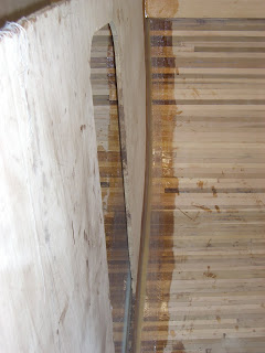
In the above picture you can see the fillet in the far bulkhead joint. It is beige in color, due to the wood flour and fumed silica added to the epoxy to thicken and create structural filler. The fillet gives the joint a radius and strength. The glass fabric can not make sharp corners.

The strips of biaxial fiberglass were cut with Janes fabric rotary cutter. Cutting with scissors causes lots of fraying and frustration.
Epoxy was mixed by the small batch and applied with cheap disposable 1" paint brushes.
The glass was applied in 3 layers.

First layer was positioned mostly on the hull, barely onto the bulkhead. The second mostly on the bulkhead, and the third equally across the filleted joint.

On close inspection you can see the fillet with the fabric wetted over it.

The frames were only filleted.

This shows the glassing and filleting and epoxy work while it is drying in the head area.

The cedar is pretty wetted out with a couple coats of epoxy and fillets at the frames.

View of the stem, glassed, wetted, and filleted.

Structural taping was used at places that will be covered by veneers, paint or trim.

The engine supports were reshaped to fit the chosen Beta Marine, and glassed into space. The glass on the hull is sanded smooth. The blue tape is covering and protecting the bronze rod/bolts that are drilled through the rear deadwood.

A bit of head scratching went into design and construction of the quarter berth.

Lots of fitting and scribing....

In and out the bunk goes....

This shows the final quarter berth with access holes in place.

Epoxy work in the engine compartment is completed. This will be partially under the cockpit. Side walls will frame out the remainder of the compartment.

Don Goodspeed came over to assist with drilling the keel bolt holes. They will hold the lead keel in place and it is important to get them as straight as possible.

The extra long bit is very intimidating.

There was worry about it being strong enough to penetrate through the floor frames and the dense deadwood. They were created with many layers of wood and epoxy.

A jig was created at each keel bolt site to help keep the shaft plumb during the drill.

Fingers hold the bit evenly spaced from the jig.

Not much error fore or aft would mean coming out the side of the floor frame.

The bit had to removed and cleaned several times for each hole.

There were a total of twelve holes drilled through the hull of the boat. Every one was a success!

We started playing around with cabinetry placement. This is looking forward into the head compartment. The cardboard cutout will be a bench covering the toilet in the forward storage/workshop/head area.

The starboard settee needs to be adjusted to cover the frame in the middle....

Placement and dimensions being critiqued.....poor Richard. The first-mate is particular!

To shape the sheer from the designed offsets, the sheer needed to be marked at the appropriate height above the DWL (designed waterline) at each station. The mark showing DWL remained visible under the epoxy on the main bulkhead. A ruler was clamped in place and a water level was used to find the correct placement of the sheer on the outside of the hull. The clear tubing (on left) was run out through a keel bolt hole and filled with water.

Here it is hanging out the bottom. The water height at the interior end was held at the right height on the ruler, and the far end was held against the outside of the hull at the correct station, and a pencil mark applied.

A thin batten painted flat black was clamped in place along the pencil marks.

This helped us in visualizing the sheer of the deck, and fairing any humps or dips.

The sheer clamp was then trimmed and the top angled to accommodate the slope of the deck.
Subscribe to:
Post Comments (Atom)
0 comments:
Post a Comment